This topic describes the following:
How Playback Synchronization Works
Example Configuration: External Triggering
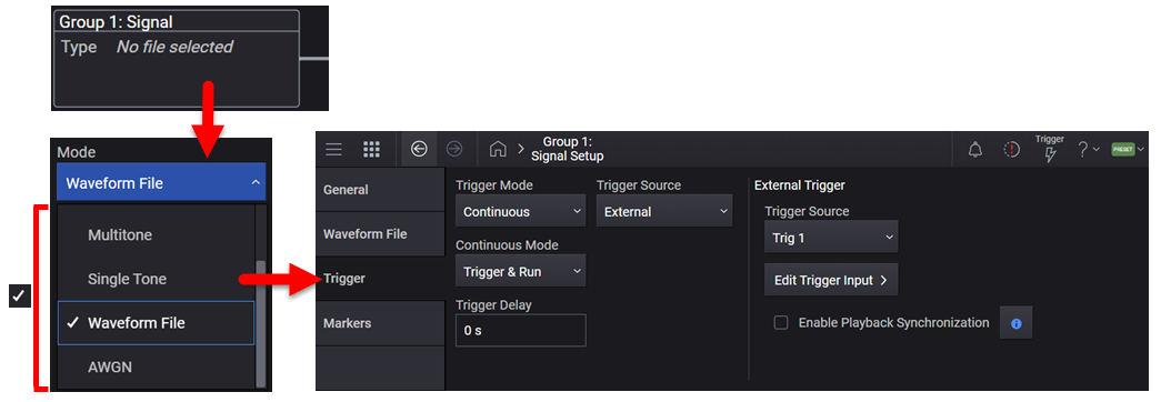
The figure below shows how to access the Triggering setup screen.
Waveform triggering configurations require two primary steps:
Selecting the Trigger Mode, which determines the behavior of the waveform when it plays.
Selecting the Trigger Source, which determines how the signal generator receives the trigger that starts the modulating waveform to play.
In addition, other triggering parameters also support your configuration.
Sets the trigger mode (or type), determining how the waveform plays when triggered. These mode selections are described in the table below.
Triggers control the playback by telling the signal generator when to play the modulating signal (waveform). Depending on the trigger settings, the waveform playback can occur once or continuously.
A trigger signal comprises both positive and negative signal transitions (states), which are also called high and low periods. You can configure the signal generator to trigger on either state of the trigger signal. It is common to have multiple trigger signals, also referred to as trigger occurrences or events, occur when the signal generator requires only a single trigger. In this situation, the signal generator’s action is based on the setting within the trigger mode.
When you select a trigger mode, you may lose the signal (carrier plus modulation) from the RF output until you trigger the waveform. This is because the signal generator sets the I and Q signals to zero volts prior to the first trigger event, which suppresses the carrier. After the first trigger event, the waveform’s final I and Q levels determine whether you will see the carrier signal or not (zero = no carrier, other values = carrier visible). At the end of most files, the final I and Q points are set to a value other than zero.
Continuous: The framed data sequence repeats continuously until you turn the signal off or select a different waveform, or trigger mode. The sequence restarts every time the previous playback is completed.
Single: The framed data sequence plays once for every trigger received.
Segment Advance: For N5186A. The trigger controls the segment advance within a waveform sequence. To use this choice, a waveform sequence must be the active waveform.
|
Available Selections for Trigger Mode |
Trigger Modes (Types) |
|
|---|---|---|
|
Continuous |
Single |
|
|
No Retrigger |
Not applicable. |
If a trigger is received early, while a waveform is playing, it will be ignored. |
|
Restart on Trigger |
Not applicable. |
If a trigger occurs while a waveform is playing, the ARB will reset and replay the waveform from the start, but there will be a gap in the playback while this is occurring. It will reset itself for every trigger it receives. |
|
Free Run |
The waveform is immediately triggered and played when Enable Vector Modulation Signal is turned on and a valid waveform file is selected. The waveform repeats until you turn off Enable Vector Modulation Signal, select another trigger, or choose another waveform file. Triggers received while the waveform is playing are ignored. |
Not applicable. |
|
Trigger & Run |
The waveform waits for a trigger before it starts playing. When the waveform receives the trigger, it plays continuously until you turn off Enable Vector Modulation Signal, select another trigger, or choose another waveform file. Subsequent triggers are ignored. |
Not applicable. |
|
Reset & Run |
The waveform waits for a trigger before it starts playing. When the waveform receives the trigger, it plays continuously. Subsequent triggers reset the waveform to the beginning. For a waveform sequence, it means the beginning of the first segment in the sequence. |
Not applicable. |
Sets the trigger source.
Bus: The trigger is initiated programmatically in the software. Use the *TRG command to initiate the trigger for all groups (channels). Use *TRG to initiate synchronous programmatic triggering of the instrument. To initiate a trigger programmatically for an individual group (channel), use the [:SOURce]:GROup<group>:SIGNal<signal>:TRIGger:IMMediate command.
Key: The trigger is initiated manually in the software, using the Trigger ![]() button. Because there is one trigger button for the instrument, if you have multiple groups (channels), all groups are triggered together.
button. Because there is one trigger button for the instrument, if you have multiple groups (channels), all groups are triggered together.
External: Enables the triggering of the waveform playing by an externally applied signal at the following connector.
On an N5186A, the connector must be configured via the External Trigger Source setting.
Immediate: Enables immediate triggering of the waveform playing.
Global Trigger (GTRigger): This trigger source must be used when synchronized playback is needed across channels in instruments with multiple channels. There is one global trigger for the instrument and therefore all signals and groups (channels) utilizing Global Trigger will be affected by changes to the Global Trigger settings.
Both KEY and BUS are software triggers and are not intended to be configured on the instrument at the same time. Even though the Trigger Source is configured on a group and signal basis, thus one signal could be configured for KEY and another for BUS, it is intended you will be either using the instrument in manual operation (via front-panel interface) or programmatically (via remote SCPI commands). You can encounter unexpected triggering if you intermix KEY and BUS triggering at the same time. They both trigger the hardware in the same way.
|
Parameter |
Description |
|---|---|
|
Trigger Delay Blanking |
When using trigger Continuous Mode of Reset & Run, or Single Mode of Restart on Trigger, if an External Trigger signal is received during the waveform playback, the playback continues during the trigger delay. Set Trigger Delay Blanking On to suppress playback during the delay period. For the N5186A, the external trigger delay blanking is on and not changeable. |
|
Playback Synchronization |
In cases where playback synchronization with another instrument or device under test is desired, enable external-trigger Playback Synchronization to ensure that the output signal is synchronous to the trigger event. Waveform samples will be skipped until internal processing is complete and playback commences. Playback Synchronization applies when Trigger Source is External, Trigger Mode is set to Continuous and Continuous Mode is set to Trigger & Run. See also, How Playback Synchronization Works. |
For N5186A:
|
Trigger Mode(s) |
Trigger Latency |
|
Continuous > Trigger & Run |
340 ns ± 75 ns |
| Continuous > Reset & Run |
To stop currently playing waveform: 340 ns ± 75 ns To start a new waveform: 340 ns ± 75 ns + Sample rate dependent delay (ns)a |
| Single > No Retrigger | 340 ns ± 75 ns |
| Single > Restart on Trigger |
To stop currently playing waveform: 340 ns ± 75 ns To start a new waveform: 340 ns ± 75 ns + Sample rate dependent delay (ns)a |
| Single > Buffered |
340 ns ± 75 ns + Buffered latency if the trigger arrives while a waveform is currently being played |
a Sample rate dependent delay (ns) = 3.333 * [ (4800 / SampleRate_MHz) + 1500 ]
In cases where playback synchronization with another instrument or device under test is desired, enable external-trigger Playback Synchronization to ensure that the output signal is synchronous to the trigger event. Waveform samples will be skipped until internal processing is complete and playback commences.
Playback Synchronization applies when Trigger Source is External, Trigger Mode is set to Continuous and Continuous Mode is set to Trigger & Run.
Playback synchronization should be used whenever you want to synchronize the N5186A's playback with a receiver, such as for bit error rate testing (BERT) and block error rate testing (BLERT). Your external controller program must be able to determine which waveform sample the N5186A will be playing at any given point in time. Without playback synchronization, this is difficult due to the variable nature of the N5186A's internal processing time, delaying the start of waveform playback.
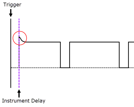
Waveform playback begins after the instrument completes internal processing. If Playback Synchronization is disabled (default state), the entire waveform is played, including the very first sample point. Disabling Playback Synchronization is recommended when triggering waveforms with durations not significantly greater than the processing time, thereby not skipping over a large percentage of sample points.
There will always be some amount of internal processing time (FPGA and electrical delays).
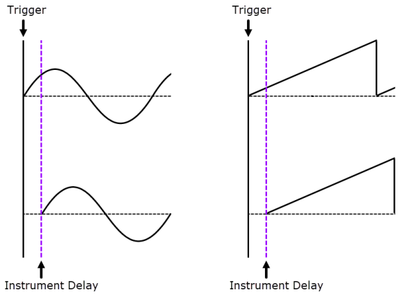
The signal calculation begins simultaneously with the external trigger event, but because of the instrument's processing time, the first samples are cut off and no signal is output. Once the internal processing time has elapsed, the output signal is synchronous to the trigger event.
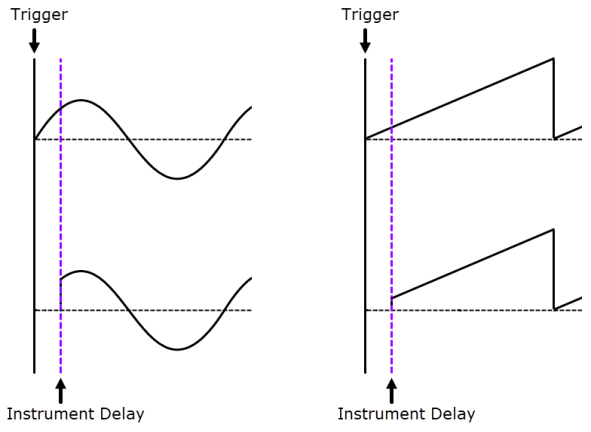
When Playback Synchronization is enabled, the instrument's internal processing time consumes (or skips over) an equivalent amount of the waveform's beginning samples, keeping the waveform synchronized with the trigger signal. This is why playback synchronization is recommended only for triggering waveforms with durations significantly greater than the processing time.
When Playback Synchronization is ON, the Trigger Delay is limited.
When Playback Synchronization is ON, DSP computation overrange may occur due to a sharp transition at the start of waveform playback. Decreasing the Scale can avoid this issue.
Use the following example to set the N5186A to output a modulated RF signal 100 milliseconds after a change in TTL state from low to high occurs at the CH 1 EXT 1 rear panel BNC connector.
Connect a BNC cable from the function generator's output port to the CH 1 EXT 1 connector on the rear panel of the N5186A.
On the N5186A's multi-touch screen, click the Signal block and select a waveform for playback:
Select Waveform File for the Mode.
Under Waveform Playback Setup, click Select to choose a waveform file.
You can set other parameters in this screen, as you desire, such as Sample Rate.
Click the Enable Signal checkbox to turn on the vector modulation and play the selected waveform.
Under Triggering, Markers & Noise, click the Trigger block and set the following parameters:
Trigger Mode: Single
Single Mode: No Retrigger
Trigger Source: External
Trigger Slope: Positive
Trigger Delay: 100 ms
On the N5186A's multi-touch screen, click the Output Mod block and verify that Enable Output Modulation is set to on (checkmarked).
On the N5186A's multi-touch screen, click the RF Output block and set the following parameters:
Frequency, as desired
Power, as desired
Enable RF Output set to on (checkmarked)
Configure the Function Generator:
Waveform: 0.1 Hz square wave
Output Level: 3.5 V to 5 V.
